The capacitor is a component which has the ability or “capacity” to store energy in the form of an electrical charge producing a potential difference (Static Voltage) across its plates, much like a small rechargeable battery.
There are many different kinds of capacitors available from very small capacitor beads used in resonance circuits to large power factor correction capacitors, but they all do the same thing, they store charge.
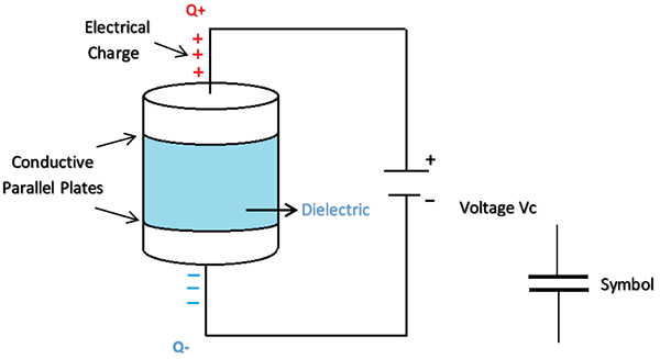
In its basic form, a capacitor consists of two or more parallel conductive (metal) plates which are not connected or touching each other, but are electrically separated either by air or by some form of a good insulating material such as waxed paper, mica, ceramic, plastic or some form of a liquid gel as used in electrolytic capacitors. The insulating layer between a capacitors plates is commonly called the Dielectric.
Due to this insulating layer, DC current can not flow through the capacitor as it blocks it allowing instead a voltage to be present across the plates in the form of an electrical charge.
The conductive metal plates of a capacitor can be either square, circular or rectangular, or they can be of a cylindrical or spherical shape with the general shape, size and construction of a parallel plate capacitor depending on its application and voltage rating.
When used in a direct current or DC circuit, a capacitor charges up to its supply voltage but blocks the flow of current through it because the dielectric of a capacitor is non-conductive and basically an insulator. However, when a capacitor is connected to an alternating current or AC circuit, the flow of the current appears to pass straight through the capacitor with little or no resistance.
There are two types of electrical charge, positive charge in the form of Protons and negative charge in the form of Electrons. When a DC voltage is placed across a capacitor, the positive (+ve) charge quickly accumulates on one plate while a corresponding and opposite negative (-ve) charge accumulates on the other plate. For every particle of +ve charge that arrives at one plate a charge of the same sign will depart from the -ve plate.
Then the plates remain charge neutral and a potential difference due to this charge is established between the two plates. Once the capacitor reaches its steady state condition,an electrical current is unable to flow through the capacitor itself and around the circuit due to the insulating properties of the dielectric used to separate the plates.
The flow of electrons onto the plates is known as the capacitors Charging Current which continues to flow until the voltage across both plates (and hence the capacitor) is equal to the applied voltage Vc. At this point the capacitor is said to be “fully charged” with electrons.
The strength or rate of this charging current is at its maximum value when the plates are fully discharged (initial condition) and slowly reduces in value to zero as the plates charge up to a potential difference across the capacitors plates equal to the source voltage.
The amount of potential difference present across the capacitor depends upon how much charge was deposited onto the plates by the work being done by the source voltage and also by how much capacitance the capacitor has and this is illustrated below.
The parallel plate capacitor is the simplest form of capacitor. It can be constructed using two metal or metallised foil plates at a distance parallel to each other, with its capacitance value in Farads, being fixed by the surface area of the conductive plates and the distance of separation between them. Altering any two of these values alters the the value of its capacitance and this forms the basis of operation of the variable capacitors.
Also, because capacitors store the energy of the electrons in the form of an electrical charge on the plates the larger the plates and/or smaller their separation the greater will be the charge that the capacitor holds for any given voltage across its plates. In other words, larger plates, smaller distance, more capacitance.
By applying a voltage to a capacitor and measuring the charge on the plates, the ratio of the charge Q to the voltage V will give the capacitance value of the capacitor and is therefore given as: C = Q/V this equation can also be re-arranged to give the familiar formula for the quantity of charge on the plates as: Q = C x V
Although we have said that the charge is stored on the plates of a capacitor, it is more exact to say that the energy within the charge is stored in an “electrostatic field” between the two plates. When an electric current flows into the capacitor, it charges up, so the electrostatic field becomes much stronger as it stores more energy between the plates.
Likewise, as the current flowing out of the capacitor, discharging it, the potential difference between the two plates decreases and the electrostatic field decreases as the energy moves out of the plates.
The property of a capacitor to store charge on its plates in the form of an electrostatic field is called the Capacitance of the capacitor. Not only that, but capacitance is also the property of a capacitor which resists the change of voltage across it.
Post time: Jul-31-2020