What are the functions and uses of capacitors? It’s all here!
Capacitor is the most common and commonly used device in circuit design. It is one of the passive components. Active devices are simply devices that require an (electrical) source. They are called active devices. Devices that do not require an (electrical) source are passive devices. . Capacitors also often play an important role in high-speed circuits.
The role and purpose of capacitors are generally many. Such as: the role of bypass, decoupling, filtering, energy storage; the role of complete oscillation, synchronization and time constant …
Let’s analyze it in detail:
1. DC blocking: the function is to prevent DC from passing and let AC pass.
2. Bypass (decoupling): Provides a low-impedance path for some paralleled components in the AC circuit.
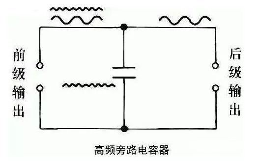

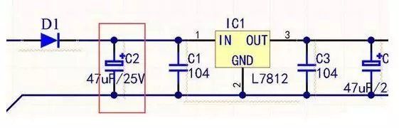
Bypass capacitor: A bypass capacitor, also known as a decoupling capacitor, is an energy storage device that provides energy to a device. It uses the frequency impedance characteristic of the capacitor (the frequency characteristic of an ideal capacitor decreases with increasing frequency) Like a water pond, it can make the output voltage uniform and reduce the load voltage fluctuation. The bypass capacitor should be as close as possible to the power supply pin and ground pin of the load device. This is an impedance requirement. Pay special attention when drawing the PCB. Only when it is close to a certain component can the voltage or other input signals be suppressed due to excessive voltage. The ground potential increase and noise, to put it plainly, is to couple the AC component of the DC power supply to the power supply ground through the capacitor, which has the effect of purifying the DC power supply. As shown in Figure C1, the bypass capacitor should be as close to IC1 as possible.
Decoupling capacitors: Decoupling capacitors take the interference of the output signal as a filtering object. Decoupling capacitors are equivalent to batteries. Use their charge and discharge so that the amplified signal will not be disturbed by sudden changes in current. Its capacity depends on the frequency of the signal and the degree of ripple suppression. The decoupling capacitor serves as a “battery” to meet the current changes in the drive circuit and avoid coupling interference.
The bypass capacitor is actually decoupled, but the bypass capacitor generally refers to a high-frequency bypass, which means that a low-impedance relief path is provided for high-frequency switching noise. The high-frequency bypass capacitor is generally small, and generally takes 0.1F, 0.01F, etc. according to the resonance frequency; while the capacity of the decoupling capacitor is generally large, which may be 10F or larger, depending on the distribution parameters in the circuit and the change in the driving current to make sure. Figure C3 is the decoupling capacitor
The difference is that the bypass is to take the interference in the input signal as the filtering object, while the decoupling is to take the interference of the output signal as the filtering object, preventing the interference signal from returning to the power supply.
3. Coupling: As a connection between two circuits, AC signals are allowed to pass through and be transmitted to the next-level circuit.
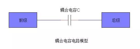
The capacitor is used as a coupling element to transfer the signal from the previous stage to the next stage, and to block the influence of the direct current from the previous stage on the subsequent stage, so that the circuit debugging is simple and the performance is stable.
If the AC signal is not amplified without capacitors, it will not change, but the operating points at all levels need to be redesigned. Due to the influence of the front and rear stages, it is very difficult to debug the operating points, which is almost impossible to achieve in multiple stages.
4. Filtering: This is very important for the circuit. The capacitors behind the CPU basically have this function.
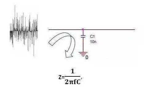
That is, the larger the frequency f, the smaller the impedance Z of the capacitor. At low frequencies, the capacitor C has a relatively large impedance Z, and the useful signal can pass smoothly. At high frequencies, the capacitor C is already very small due to the impedance Z, which is equivalent to short-circuiting high-frequency noise to GND.
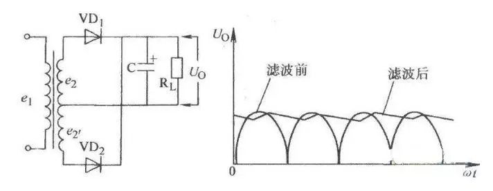
 Filtering effect: Ideal capacitor. The larger the capacitor, the smaller the impedance and the higher the frequency of passing. Electrolytic capacitors are generally more than 1F. The inductance component is very large, so the impedance will be high when the frequency is high. We often see that sometimes we see an electrolytic capacitor with a large capacitance connected in parallel with a small capacitor. In fact, a large capacitor passes low frequencies, and a small capacitor passes high frequencies. In this way, high and low frequencies can be fully filtered. The higher the capacitor frequency, the greater the attenuation. The capacitor is like a pond. A few drops of water are not enough to cause it to change greatly. That is to say, the voltage fluctuation is not when you are very large. The voltage can be buffered, as shown in Figure C2.
5. Temperature compensation: To compensate for the influence of other components’ insufficient adaptability to temperature, perform compensation to improve the stability of the circuit.
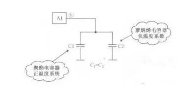
Analysis: Since the capacity of the timing capacitor determines the oscillation frequency of the line oscillator, the capacity of the timing capacitor is required to be very stable and does not change with the change of environmental humidity, so that the oscillation frequency of the line oscillator can be stabilized. Therefore, a capacitive release coupling with positive and negative temperature coefficients is used for temperature complementation.
When the operating temperature increases, the capacity of Cl increases, while the capacity of C2 decreases. The total capacity of two capacitors in parallel is the sum of the two capacitors’ capacity, because one capacity is increasing and the other is decreasing. , So the total capacity is basically unchanged.
Similarly, when the temperature decreases, the capacity of one capacitor decreases and the other increases. The total capacity is basically unchanged, which stabilizes the oscillation frequency and achieves the purpose of temperature compensation.
6. Timing: The capacitor and resistor are used together to determine the time constant of the circuit.
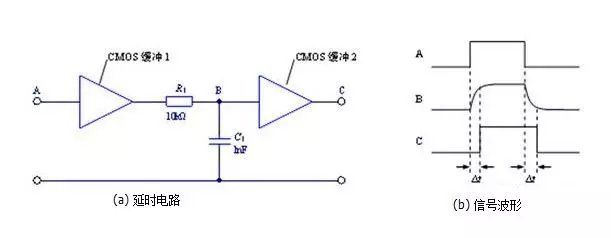
When the input signal transitions from low to high, it is input to the RC circuit after buffering 1. The characteristics of capacitor charging make the signal at point B not to jump immediately following the input signal, but to have a gradually increasing process. When it becomes large to a certain extent, buffer 2 flips over and gets a delayed low-to-high transition at the output.
Time constant: Take the common RC series circuit as an example. When the input signal voltage is applied to the input terminal, the voltage on the capacitor gradually rises. The charging current decreases as the voltage rises. The resistor R and capacitor C are connected in series to the input signal VI, and the capacitor C outputs the signal V0. When the value of RC (τ) and the input square wave width tW are satisfied: τ 》》 TW, this circuit is called integration circuit
7. Tuning: System tuning of frequency-related circuits, such as mobile phones, radios, and televisions.
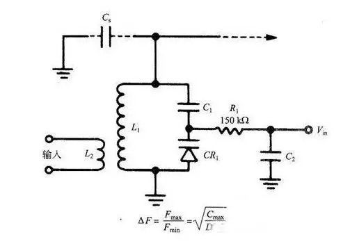
Tuning circuit of varactor diode
Because the resonant frequency of the tuned oscillating circuit is a function of lc, we find that the ratio of the maximum to the minimum resonant frequency of the oscillating circuit changes with the square root of the capacitance ratio. The capacitance ratio here refers to the ratio of the capacitance when the reverse bias voltage is the smallest and the capacitance when the reverse bias voltage is the largest. Therefore, the tuning characteristic curve (bias-resonant frequency) of the circuit is basically a parabola.
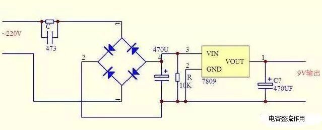
8. Rectification: Open or close the semi-closed conductor switching element at a predetermined time.
9. Energy storage: Store electrical energy for release when necessary.
Such as camera flash, heating equipment and so on. (The energy storage level of some capacitors is now close to the level of lithium batteries. The energy stored in a capacitor can be used by a mobile phone for a day.
Energy storage effect: Generally, electrolytic capacitors have the function of energy storage. For the special energy storage capacitor, the mechanism of capacitor energy storage is electric double layer capacitor and Faraday capacitor. Its main form is super capacitor energy storage. Among them, super capacitor is a capacitor using the principle of electric double layer. When the two electrode plates of a capacitor are the same as ordinary capacitors, the positive electrode of the electrode plate stores positive charges and the negative plate stores negative charges. Under the action of the electric field generated by the charges on the two electrode plates of the super capacitor, the Opposite charges are formed at the interface to balance the internal electric field of the electrolyte. This positive and negative charges are arranged at opposite positions on the contact surface between two different phases, with extremely short gaps between the positive and negative charges. This charge distribution layer is called an electric double layer, so the capacitance is very large.
Post time: Mar-09-2020